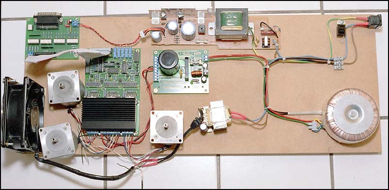
Fig 1. During Testing
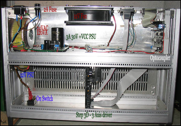
Fig 2. Layout
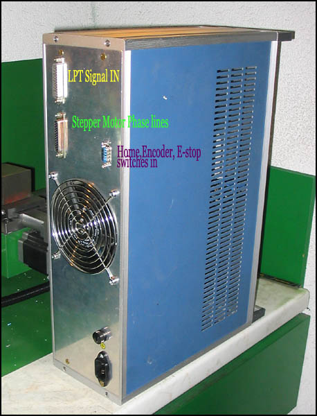
Fig 3. Finished driver.
FrankenSieg's Driver
I bought the L297 / L298 based stepper driver kit from Thorsten Ostermann's NC-Step. This Product, Step-3D is a three axis 2A half-stepping, chopper driver for bipolar stepper motors. At the same time, I also got NC-Step's Parallel port Optocoupler kit, and 3A 30V power supply kit.
I have the highest regard for Thorsten Ostermann and his company. At the time I built the Step-3D, it was only the second electronic kit I had ever soldered, and I screwed up just about everything, even managing to solder one resister array backwards, twice in a row. Thorsten was very forthcominng with advice and trouble shooting assistance.
The Optocoupler from NC-Step has pull up resisters and schmitt triggers on all the output lines, making it usable even on modern laptops with weak parallel ports.
The Power supply is very convenient as it combines a 5V regulated logic supply with the 30V unregulated muscle power.
After assembly I set up the controller on a board for testing. Three old 5V 1A Argentinien Steppers were used for testing. It was a good idea to lay out the components, as I had made lots of mistakes (most of which were covered with warnings in the instructions).
I got lucky at my local scrap yard. Siemens had scrapped a whole bunch of rack mounted stuff, so I picked up a nice, double height, modular aluminium 19" instrument case for €15. I spilt this into two cases.
Cooling is provided by a nice big 12V housing fan. This was €2.50 from the same scrap yard.
The PC side of the Optocoupler needs in independant 5V supply. Rather than tapping this off the game port (There are no power available from the LPT), I bought a 12V wall wart power adapter from a second hand store for €1.50, and pulled it apart. It was a simple transformer, four diodes bridge and cap. This power supply also drives the cooling fan.The NC-Step optocoupler has provision for a 7805 5V regulator on board.
The 5V logic power for the driver side of the optocoupler is provided from the driver down the 26th line of the ribbon cable.
I currently have a D-sub 25 pin connector for the wiring to the motors and spindle encoder. I not too happy with this, as I have had pins back out on this. I would like to upgrade to one XLR connentor per motor, and a D-sub for the home switches and encoder.