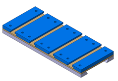
7X12 Mini-Lathe T-slotted Cross-slide.
Introduction
During the CNC conversion of FrankenSieg, it became increasingly obvious that T-Slots in the cross slide would greatly increase the flexiblity of this machine. As this is, for the foreseeable future, the only machine I have space for, it is imperative that it be as flexible as possible. To this end, four T-slots were decided upon.
At first look, it seemed attractive to just add T-slot strips to the existing cross slide. After modelling this design in CAD, it became obvious that this idea was flawed. The standard cast iron cross slide has only 8mm between the inner corner of the dovetail and the out side. This would have led to insufficient edge distance for the screws. Mounting from below would have only allowed M4 screws due to the smaller counterbore, and have caused problems with access for adjusting the leadscrew nut. The large hole left by the compound mount nut would act as a giant swarf trap. The raised T-slots would have reduced the max swing of the lathe.
In discussion with JW Early, he recommended a competely new built up cross-slide, as detailed by Martin Cleve for Model Engineer in 1958. Studying this design, it became apparent that this wheel was already long invented. Of particular interest was the comment that the 1/4" base plate was overkill, and could be replaced with a 1/8" plate. This would allow a design which adds no height compared to the standard Sieg part.
The following modifications to the Cleeve design were made for the 7X12 Sieg. All dimensions were converted to metric. The width was set at 75mm, an increase of 5mm overhang either side from standard. This addressed the problem of edge distance to the dovetail and edge. As Sieg were very conservative with the cross slide travel, the new slot slide will be 180mm long as opposed to the original 154mm. The cross slide travel with two gib's engaged is 100mm. The CNC conversion included milling the saddle to increase the cross slide travel, and a new, longer spacer block. The longer cross slide leads to the deletion of the Sieg rear chip guard. The existing gib strip is retained. The four T slots are 8mm wide and 44mm apart.
The 10x3mm LH trapezoid leadscrew used in the CNC conversion has two nuts in an antibacklash configuration as drawn by Will Hamlyn. The nut mounting holes have been moved forward from the Sieg cross slide location, to keep them clear of the T-slots.

